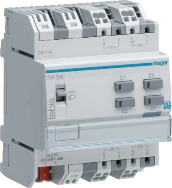
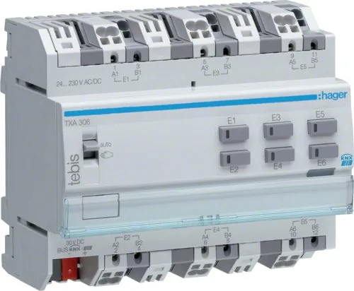
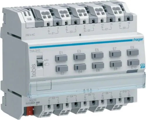
6LE000121E 6LE000121E 6LE000121E
6LE000121E
r a
Module 6 entrées 24...230
t e
Binäreingang 6-fach 24...230
s z
4-fold input module 24...230
o i
Module 4 ingangen 24...230
k y
Modulo da 4 ingressi 24...230
AA
F
Informations système
Cet appareil est un pr
conforme au standard KNX. Des connaissances
spécialisées détaillées dispensées par le biais
de formations KNX sont nécessaires pour la
compréhension du système. La pr
l‘installation et la mise en service de l‘appareil
s‘eectuent à l‘aide d‘un logiciel certifié KNX.
Description fonctionnelle
Les modules d’entr
d’interfacer des contacts libres de pot
alimentés en 24...230 V AC/DC avec le bus KNX.
Par e
automatismes ou contacts d’alarme peuvent ainsi être
rendus communicants.
•
automatique du type de circuit raccor
AC/DC ou libre de potentiel).
• Détection de coupure sect
permet de filtrer les fausses alarmes dues à la
coupure pour les entrées raccor
phase de référence.
Les fonctions pr
de la configuration et du par
Légende
1
TXA310
30V DC
-
+
Bus
auto
E8
E7
E10 E10
E9 E9
13
15
E7
17
E9
19
14
16
18 20
C8 C10
7
9
E5
11
8
10
12
E6
E2
E1
E4 E4
E3 E3
E6 E6
E5 E5
1
3
E1
5
E3
2
4
6
E2 E4
auto
TXA310
30V D C
-
+
Bus
auto
E8
E7
E10 E10
E9 E9
13
15
E7
17
E9
19
14
16
18 20
C8 C10
7
9
E5
11
8
10
12
E6
E2
E1
E4 E4
E3 E3
E6 E6
E5 E5
1
3
E1
5
E3
2
4
6
E2 E4
E10 E10
auto
Ech 60%
L3
L2
L1
N
L3
L2
L1
N
auto
E6
E5
E4
E3
E8 E8
E7 E7
E10 E10
E9 E9
TXA 310
E2
E1
30 V DC
-
+
BUS
/
19
1
35 79 11 13 15
46 81 01 21 41 6
2
17
18 20
NL
E1
NL
E2
NL
E4
NL
E3
NL
E5
NL
E7
NL
E9
NL
E6
NL
E8
NL
E10
230 V A C
1
2
3
4
Commutateur
2
TXA310
30V DC
-
+
Bus
auto
E8
E7
E10 E10
E9 E9
13
15
E7
17
E9
19
14
16
18 20
C8 C10
7
9
E5
11
8
10
12
E6
E2
E1
E4 E4
E3 E3
E6 E6
E5 E5
1
3
E1
5
E3
2
4
6
E2 E4
auto
TXA310
30V D C
-
+
Bus
auto
E8
E7
E10 E10
E9 E9
13
15
E7
17
E9
19
14
16
18 20
C8 C10
7
9
E5
11
8
10
12
E6
E2
E1
E4 E4
E3 E3
E6 E6
E5 E5
1
3
E1
5
E3
2
4
6
E2 E4
E10 E10
auto
Ech 60%
L3
L2
L1
N
L3
L2
L1
N
auto
E6
E5
E4
E3
E8 E8
E7 E7
E10 E10
E9 E9
TXA 310
E2
E1
30 V DC
-
+
BUS
/
19
1
35 79 11 13 15
46 81 01 21 41 6
2
17
18 20
NL
E1
NL
E2
NL
E4
NL
E3
NL
E5
NL
E7
NL
E9
NL
E6
NL
E8
NL
E10
230 V A C
1
2
3
4
LED
3
TXA310
30V DC
-
+
Bus
auto
E8
E7
E10 E10
E9 E9
13
15
E7
17
E9
19
14
16
18 20
C8 C10
7
9
E5
11
8
10
12
E6
E2
E1
E4 E4
E3 E3
E6 E6
E5 E5
1
3
E1
5
E3
2
4
6
E2 E4
auto
TXA310
30V D C
-
+
Bus
auto
E8
E7
E10 E10
E9 E9
13
15
E7
17
E9
19
14
16
18 20
C8 C10
7
9
E5
11
8
10
12
E6
E2
E1
E4 E4
E3 E3
E6 E6
E5 E5
1
3
E1
5
E3
2
4
6
E2 E4
E10 E10
auto
Ech 60%
L3
L2
L1
N
L3
L2
L1
N
auto
E6
E5
E4
E3
E8 E8
E7 E7
E10 E10
E9 E9
TXA 310
E2
E1
30 V DC
-
+
BUS
/
19
1
35 79 11 13 15
46 81 01 21 41 6
2
17
18 20
NL
E1
NL
E2
NL
E4
NL
E3
NL
E5
NL
E7
NL
E9
NL
E6
NL
E8
NL
E10
230 V A C
1
2
3
4
BP
4
TXA310
30V DC
-
+
Bus
auto
E8
E7
E10 E10
E9 E9
13
15
E7
17
E9
19
14
16
18 20
C8 C10
7
9
E5
11
8
10
12
E6
E2
E1
E4 E4
E3 E3
E6 E6
E5 E5
1
3
E1
5
E3
2
4
6
E2 E4
auto
TXA310
30V D C
-
+
Bus
auto
E8
E7
E10 E10
E9 E9
13
15
E7
17
E9
19
14
16
18 20
C8 C10
7
9
E5
11
8
10
12
E6
E2
E1
E4 E4
E3 E3
E6 E6
E5 E5
1
3
E1
5
E3
2
4
6
E2 E4
E10 E10
auto
Ech 60%
L3
L2
L1
N
L3
L2
L1
N
auto
E6
E5
E4
E3
E8 E8
E7 E7
E10 E10
E9 E9
TXA 310
E2
E1
30 V DC
-
+
BUS
/
19
1
35 79 11 13 15
46 81 01 21 41 6
2
17
18 20
NL
E1
NL
E2
NL
E4
NL
E3
NL
E5
NL
E7
NL
E9
NL
E6
NL
E8
NL
E10
230 V A C
1
2
3
4
BP lumineux d’adressage physique
F
En position
TXA310
30V DC
-
+
Bus
auto
E8
E7
E10 E10
E9 E9
13
15
E7
17
E9
19
14
16
18 20
C8 C10
7
9
E5
11
8
10
12
E6
E2
E1
E4 E4
E3 E3
E6 E6
E5 E5
1
3
E1
5
E3
2
4
6
E2 E4
auto
TXA310
30V D C
-
+
Bus
auto
E8
E7
E10 E10
E9 E9
13
15
E7
17
E9
19
14
16
18 20
C8 C10
7
9
E5
11
8
10
12
E6
E2
E1
E4 E4
E3 E3
E6 E6
E5 E5
1
3
E1
5
E3
2
4
6
E2 E4
E10 E10
auto
Ech 60%
L3
L2
L1
N
L3
L2
L1
N
auto
E6
E5
E4
E3
E8 E8
E7 E7
E10 E10
E9 E9
TXA 310
E2
E1
30 V DC
-
+
BUS
/
19
1
35 79 11 13 15
46 81 01 21 41 6
2
17
18 20
NL
E1
NL
E2
NL
E4
NL
E3
NL
E5
NL
E7
NL
E9
NL
E6
NL
E8
NL
E10
230 V A C
1
2
3
4
du commutateur 1 , les BP 3
permettent de simuler les contacts r
L2 dépend de la configur
et du paramétr
des LED 2 indique le chargement d’un mauvais
logiciel d’application.
Détection du type de contact raccordé
Le module est capable de détect
le type de tension r
continue tension alternative ou absence de t
pour un contact libre de potentiel).
A la premièr
repr
tension r
nécessaire de mémoriser le type de tension dét
Suivre la pr
1.
2.
3.
4.
5.
6.
Après un r
la procédur
type de circuit r
Caract techniques / T Daten / T
characteristics / T kenmerken / Car tecniche
TXA306
T
aux entrées
Signal-
spannung
Signal voltage
Signaal-
spanning
T
segnale
24 ... 230
AC (50Hz) / DC
Distance
maximun de
raccor
Leitungslänge
Maximum
connection
distance per
input
Maximum
aansluitafstand
per ingang
Distanza
massima tra
contatto
e ingresso
100 m
Alimentation
produit
V
spannung
Supply voltage
V
spanning
T
alimentazione
30 V DC
Consommation
bus typique
T
belastung
Busline typ.
consumption
Buslijn typ.
verbruik
Consumo
Bus typ.
6 mA
Consommation
bus maximale
Max. Bus
belastung
Busline max
consumption
Buslijn max
verbruik
Consumo
Bus max
7 mA
Encombrement Abmessung Dimensions Afmetingen Ingombro 6 x 17,5 mm
Indice de
protection
Schutzart
Degree of
protection
Beschermings-
graad
Grado di
prote
IP 20
IP 30 (plastron)
T° de
fonctionnement
Betriebs-
temper
Operating
temper
Bedirijfs-
temper
T° di
funzionamento
0 °C
+ 45
T° de stockage
Lager-
temper
Stor
temper
Opslag-
temper
T° di
stoccaggio
- 20 °C
➡ + 70
Mode de
transmission
KNX
Kommunikation-
smodus KNX
Communication
mode KNX
Communicatie-
modus KNX
Media di
comunicazione
KNX
TP1
Mode de
configuration
KNX
Konfigurations-
modus KNX
Configuration
mode KNX
Configuratie-
modus KNX
Modalità di
configurazione
KNX
S-mode
Raccordement / Anschluss / Connections /
Ligaçoes / Anslutning
0,75
➡ 2,5 mm²
TXA306
30V DC
-
+
Bus
auto
E4
E3
E6 E6
E5 E5
9
E5
11
10
12
E6
5
E3
7
6
8
E4
E2 E2
E1 E1
1
3
E1
2
4
E2
E10 E10
auto
auto
Ech 60%
+
N
48 V AC
24 V DC
230 V AC
L
-
L2
N1
L1
N2
L3
N3
TXA306
30V DC
-
+
Bus
auto
E4
E3
E6E6
E5E5
9
E5
11
10
12
E6
5
E3
7
6
8
E4
E2E2
E1E1
1
3
E1
2
4
E2
+
-
+
48 V AC
24 V DC
230 V AC
-
L2
N1
L1
N2
L3
N3
1
3
4
2
Bouton poussoir d’adressage physique 4
Appuyer sur le bouton poussoir lumineux 4 pour
réaliser l’adr
la présence bus
voyant allumé = présence bus et pr
adressage physique.
Perturbation du signal d’entr
Dans certains types d’installations (chemins de
câbles, goulottes ou câbles multi conducteurs), il est
nécessaire de veiller à r
fort/courant faible. La pr
au réseau d’alimentation de l’installation (230V ou
400V) avec les fils de signal connectés aux entrées
du TXA306 peut conduire à cr
dans les fils connectés aux entrées et donc génér
des commandes non désirées.
L
entrées permet également de limiter le phénomène de
courants induits.
Appareil à installer uniquement par un
installateur électricien selon les normes
d’installation en vigueur dans le pays.
Respecter les règles d’installation TB
Si plusieurs entrées libr
connectées, elles doivent rest
indépendantes (pas de point commun).
L
toutefois possible dans le cas d’utilisation de
contacts alimentés en 24…230
Ne pas connecter de boutons-poussoirs
ou d’interrupteurs à voyant sur les entr
du produit.
Ne pas connecter de voyants en par
des contacts, boutons-poussoirs ou
interrupteurs connect
EE
F
Systeminformationen
Dieses Gerät ist ein P
entspricht dem KNX-Standard. Spezifische detailliert
Kenntnisse, welche durch KNX-Schulungen
erworben werden, sind erforderlich, um das Syst
zu verstehen. Die Pr
Inbetriebnahme des Geräts erfolgen mithilfe eines
zertifizierten KNX-P
F
Die Universal-Eingangsmodule fungieren als
Schnittstelle zwischen spannungsfreien bzw
24...230 V AC/DC-gespeisten K
KNX-Bus. Auf diese Weise k
T
Alarmkontakte in die K
werden.
• 6 voneinander unabhängige Kanäle mit
automatischer Erkennung des angeschlossenen
Kreistyps (24...230V AC/DC oder spannungsfrei).
• Netzstromausfallmeldefunktion :
Diese Meldefunktion dient zum Filtern von blindem
Alarm aufgrund von Stromausfall an an derselben
Bezugsphase angeschlossenen Eingängen.
Die genauen F
der jeweiligen Konfigur
Par
Legende
1
TXA310
30V DC
-
+
Bus
auto
E8
E7
E10 E10
E9 E9
13
15
E7
17
E9
19
14
16
18 20
C8 C10
7
9
E5
11
8
10
12
E6
E2
E1
E4 E4
E3 E3
E6 E6
E5 E5
1
3
E1
5
E3
2
4
6
E2 E4
auto
TXA310
30V D C
-
+
Bus
auto
E8
E7
E10 E10
E9 E9
13
15
E7
17
E9
19
14
16
18 20
C8 C10
7
9
E5
11
8
10
12
E6
E2
E1
E4 E4
E3 E3
E6 E6
E5 E5
1
3
E1
5
E3
2
4
6
E2 E4
E10 E10
auto
Ech 60%
L3
L2
L1
N
L3
L2
L1
N
auto
E6
E5
E4
E3
E8 E8
E7 E7
E10 E10
E9 E9
TXA 310
E2
E1
30 V DC
-
+
BUS
/
19
1
35 79 11 13 15
46 81 01 21 41 6
2
17
18 20
NL
E1
NL
E2
NL
E4
NL
E3
NL
E5
NL
E7
NL
E9
NL
E6
NL
E8
NL
E10
230 V A C
1
2
3
4
Schalter
2
TXA310
30V DC
-
+
Bus
auto
E8
E7
E10 E10
E9 E9
13
15
E7
17
E9
19
14
16
18 20
C8 C10
7
9
E5
11
8
10
12
E6
E2
E1
E4 E4
E3 E3
E6 E6
E5 E5
1
3
E1
5
E3
2
4
6
E2 E4
auto
TXA310
30V D C
-
+
Bus
auto
E8
E7
E10 E10
E9 E9
13
15
E7
17
E9
19
14
16
18 20
C8 C10
7
9
E5
11
8
10
12
E6
E2
E1
E4 E4
E3 E3
E6 E6
E5 E5
1
3
E1
5
E3
2
4
6
E2 E4
E10 E10
auto
Ech 60%
L3
L2
L1
N
L3
L2
L1
N
auto
E6
E5
E4
E3
E8 E8
E7 E7
E10 E10
E9 E9
TXA 310
E2
E1
30 V DC
-
+
BUS
/
19
1
35 79 11 13 15
46 81 01 21 41 6
2
17
18 20
NL
E1
NL
E2
NL
E4
NL
E3
NL
E5
NL
E7
NL
E9
NL
E6
NL
E8
NL
E10
230 V A C
1
2
3
4
LED
3
TXA310
30V DC
-
+
Bus
auto
E8
E7
E10 E10
E9 E9
13
15
E7
17
E9
19
14
16
18 20
C8 C10
7
9
E5
11
8
10
12
E6
E2
E1
E4 E4
E3 E3
E6 E6
E5 E5
1
3
E1
5
E3
2
4
6
E2 E4
auto
TXA310
30V D C
-
+
Bus
auto
E8
E7
E10 E10
E9 E9
13
15
E7
17
E9
19
14
16
18 20
C8 C10
7
9
E5
11
8
10
12
E6
E2
E1
E4 E4
E3 E3
E6 E6
E5 E5
1
3
E1
5
E3
2
4
6
E2 E4
E10 E10
auto
Ech 60%
L3
L2
L1
N
L3
L2
L1
N
auto
E6
E5
E4
E3
E8 E8
E7 E7
E10 E10
E9 E9
TXA 310
E2
E1
30 V DC
-
+
BUS
/
19
1
35 79 11 13 15
46 81 01 21 41 6
2
17
18 20
NL
E1
NL
E2
NL
E4
NL
E3
NL
E5
NL
E7
NL
E9
NL
E6
NL
E8
NL
E10
230 V A C
1
2
3
4
Taster
4
TXA310
30V DC
-
+
Bus
auto
E8
E7
E10 E10
E9 E9
13
15
E7
17
E9
19
14
16
18 20
C8 C10
7
9
E5
11
8
10
12
E6
E2
E1
E4 E4
E3 E3
E6 E6
E5 E5
1
3
E1
5
E3
2
4
6
E2 E4
auto
TXA310
30V D C
-
+
Bus
auto
E8
E7
E10 E10
E9 E9
13
15
E7
17
E9
19
14
16
18 20
C8 C10
7
9
E5
11
8
10
12
E6
E2
E1
E4 E4
E3 E3
E6 E6
E5 E5
1
3
E1
5
E3
2
4
6
E2 E4
E10 E10
auto
Ech 60%
L3
L2
L1
N
L3
L2
L1
N
auto
E6
E5
E4
E3
E8 E8
E7 E7
E10 E10
E9 E9
TXA 310
E2
E1
30 V DC
-
+
BUS
/
19
1
35 79 11 13 15
46 81 01 21 41 6
2
17
18 20
NL
E1
NL
E2
NL
E4
NL
E3
NL
E5
NL
E7
NL
E9
NL
E6
NL
E8
NL
E10
230 V A C
1
2
3
4
Leuchttaster zur physikalischen
Adressierung
F
Steht der Schalter 1 , auf Manu (
TXA310
30V DC
-
+
Bus
auto
E8
E7
E10 E10
E9 E9
13
15
E7
17
E9
19
14
16
18 20
C8 C10
7
9
E5
11
8
10
12
E6
E2
E1
E4 E4
E3 E3
E6 E6
E5 E5
1
3
E1
5
E3
2
4
6
E2 E4
auto
TXA310
30V D C
-
+
Bus
auto
E8
E7
E10 E10
E9 E9
13
15
E7
17
E9
19
14
16
18 20
C8 C10
7
9
E5
11
8
10
12
E6
E2
E1
E4 E4
E3 E3
E6 E6
E5 E5
1
3
E1
5
E3
2
4
6
E2 E4
E10 E10
auto
Ech 60%
L3
L2
L1
N
L3
L2
L1
N
auto
E6
E5
E4
E3
E8 E8
E7 E7
E10 E10
E9 E9
TXA 310
E2
E1
30 V DC
-
+
BUS
/
19
1
35 79 11 13 15
46 81 01 21 41 6
2
17
18 20
NL
E1
NL
E2
NL
E4
NL
E3
NL
E5
NL
E7
NL
E9
NL
E6
NL
E8
NL
E10
230 V A C
1
2
3
4
), dienen die
T3 zum Simulieren der angeschlossenen
Kontakte. Der Z2 hängt von
Konfiguar
Das Blinken aller 2 -LEDs besagt, dass die falsche
Anwendungssoftware geladen wur
Erkennung der Art des angeschlossenen
Kontakts
Das Modul ist in der Lage, die Art der an
jedem Eingang angeschlossenen Spannung
(Gleichspannung, Wechselspannung oder keine
anliegende Spannung bei einem potentialfreien
Kontakt) automatisch zu erkennen.
Bei der ersten Pr
Neuprogr
angeschlossenen Spannungsart oder nach einem
Neustart ist es notwendig, die erkannte Spannungsart
zu speichern.
Befolgen Sie dazu das folgende V
1.
2.
3.
4.
5.
6.
Nach einem Neustart des Produkts (z. B. Busausfall)
ist kein erneuter Speichervorgang erfor
wenn die Art der angeschlossenen Spannung nicht
geändert wurde.
T 4
Drücken Sie den Leuchttast4 , um die
physikalische Adressierung des Ger
oder das Anliegen des Busses zu überprüfen
Leuchte ein = Bus liegt an, physikalische
Adressierung läuft.
Störung des Eingangssignals
Bei bestimmten Installationsarten (Kabelkanäle oder
Mehrleiterkabel) muss auf die T
und Schwachstrom geachtet
Leitungen, die an das Str
Installation (230V oder 400V) angeschlossen sind, zu
den an die Eingänge des TXA306 angeschlossenen
Signalleitungen kann zu induzierten Strömen in den
an die Eingänge angeschlossenen Leitungen führ
und somit unerwünschte Befehle erzeugen.
Durch die V
den Anschluss der Eingänge lässt sich auch das
Phänomen der induzierten Ströme begr
Einbau und Montage dürfen nur durch eine
Elektrofachkr
Installationsnormen des Landes erfolgen.
Schutzmaßnahme SEL
Bei V
Kontakte müssen diese vollständig
getrennt sein (keine gemeinsame L
möglich).
Die V
Leitung ist jedoch möglich bei V
von Kontakten mit 24...230
Schließen Sie keine Drucktaster oder
Schalter mit Kontr
des Pr
Schließen Sie keine Kontr
zu den an den Eingängen angeschlossenen
Kontakten, Drucktast
ZZ
F
System information
This device is a product of KNX system and complies
with KNX guidelines. Detailed, specialised knowledge
obtained through specific KNX tr
requir
device is progr
certified KNX software.
F
Universal input modules allow interfacing contacts
free of potential or supplied with 24… 230V A
power by bus KNX. Then, pushbuttons, switches,
automatisms or alarm contacts can be made
communicating.
• 6 independent channels with automatic recognition
of the type of connected circuit (24… 230V A
circuit free of potential).
• P
alarms due to cut-o of all inputs connected on the
same reference phase.
The particular functions of each product depend
on the configuration and the set-up.
Caption
1
TXA310
30V DC
-
+
Bus
auto
E8
E7
E10 E10
E9 E9
13
15
E7
17
E9
19
14
16
18 20
C8 C10
7
9
E5
11
8
10
12
E6
E2
E1
E4 E4
E3 E3
E6 E6
E5 E5
1
3
E1
5
E3
2
4
6
E2 E4
auto
TXA310
30V D C
-
+
Bus
auto
E8
E7
E10 E10
E9 E9
13
15
E7
17
E9
19
14
16
18 20
C8 C10
7
9
E5
11
8
10
12
E6
E2
E1
E4 E4
E3 E3
E6 E6
E5 E5
1
3
E1
5
E3
2
4
6
E2 E4
E10 E10
auto
Ech 60%
L3
L2
L1
N
L3
L2
L1
N
auto
E6
E5
E4
E3
E8 E8
E7 E7
E10 E10
E9 E9
TXA 310
E2
E1
30 V DC
-
+
BUS
/
19
1
35 79 11 13 15
46 81 01 21 41 6
2
17
18 20
NL
E1
NL
E2
NL
E4
NL
E3
NL
E5
NL
E7
NL
E9
NL
E6
NL
E8
NL
E10
230 V A C
1
2
3
4
Switch
2
TXA310
30V DC
-
+
Bus
auto
E8
E7
E10 E10
E9 E9
13
15
E7
17
E9
19
14
16
18 20
C8 C10
7
9
E5
11
8
10
12
E6
E2
E1
E4 E4
E3 E3
E6 E6
E5 E5
1
3
E1
5
E3
2
4
6
E2 E4
auto
TXA310
30V D C
-
+
Bus
auto
E8
E7
E10 E10
E9 E9
13
15
E7
17
E9
19
14
16
18 20
C8 C10
7
9
E5
11
8
10
12
E6
E2
E1
E4 E4
E3 E3
E6 E6
E5 E5
1
3
E1
5
E3
2
4
6
E2 E4
E10 E10
auto
Ech 60%
L3
L2
L1
N
L3
L2
L1
N
auto
E6
E5
E4
E3
E8 E8
E7 E7
E10 E10
E9 E9
TXA 310
E2
E1
30 V DC
-
+
BUS
/
19
1
35 79 11 13 15
46 81 01 21 41 6
2
17
18 20
NL
E1
NL
E2
NL
E4
NL
E3
NL
E5
NL
E7
NL
E9
NL
E6
NL
E8
NL
E10
230 V A C
1
2
3
4
LED
3
TXA310
30V DC
-
+
Bus
auto
E8
E7
E10 E10
E9 E9
13
15
E7
17
E9
19
14
16
18 20
C8 C10
7
9
E5
11
8
10
12
E6
E2
E1
E4 E4
E3 E3
E6 E6
E5 E5
1
3
E1
5
E3
2
4
6
E2 E4
auto
TXA310
30V D C
-
+
Bus
auto
E8
E7
E10 E10
E9 E9
13
15
E7
17
E9
19
14
16
18 20
C8 C10
7
9
E5
11
8
10
12
E6
E2
E1
E4 E4
E3 E3
E6 E6
E5 E5
1
3
E1
5
E3
2
4
6
E2 E4
E10 E10
auto
Ech 60%
L3
L2
L1
N
L3
L2
L1
N
auto
E6
E5
E4
E3
E8 E8
E7 E7
E10 E10
E9 E9
TXA 310
E2
E1
30 V DC
-
+
BUS
/
19
1
35 79 11 13 15
46 81 01 21 41 6
2
17
18 20
NL
E1
NL
E2
NL
E4
NL
E3
NL
E5
NL
E7
NL
E9
NL
E6
NL
E8
NL
E10
230 V A C
1
2
3
4
Pushbutton
4
TXA310
30V DC
-
+
Bus
auto
E8
E7
E10 E10
E9 E9
13
15
E7
17
E9
19
14
16
18 20
C8 C10
7
9
E5
11
8
10
12
E6
E2
E1
E4 E4
E3 E3
E6 E6
E5 E5
1
3
E1
5
E3
2
4
6
E2 E4
auto
TXA310
30V D C
-
+
Bus
auto
E8
E7
E10 E10
E9 E9
13
15
E7
17
E9
19
14
16
18 20
C8 C10
7
9
E5
11
8
10
12
E6
E2
E1
E4 E4
E3 E3
E6 E6
E5 E5
1
3
E1
5
E3
2
4
6
E2 E4
E10 E10
auto
Ech 60%
L3
L2
L1
N
L3
L2
L1
N
auto
E6
E5
E4
E3
E8 E8
E7 E7
E10 E10
E9 E9
TXA 310
E2
E1
30 V DC
-
+
BUS
/
19
1
35 79 11 13 15
46 81 01 21 41 6
2
17
18 20
NL
E1
NL
E2
NL
E4
NL
E3
NL
E5
NL
E7
NL
E9
NL
E6
NL
E8
NL
E10
230 V A C
1
2
3
4
Physical addressing illuminated
pushbutton
Operation
While the switch 1 is in position
TXA310
30V DC
-
+
Bus
auto
E8
E7
E10 E10
E9 E9
13
15
E7
17
E9
19
14
16
18 20
C8 C10
7
9
E5
11
8
10
12
E6
E2
E1
E4 E4
E3 E3
E6 E6
E5 E5
1
3
E1
5
E3
2
4
6
E2 E4
auto
TXA310
30V D C
-
+
Bus
auto
E8
E7
E10 E10
E9 E9
13
15
E7
17
E9
19
14
16
18 20
C8 C10
7
9
E5
11
8
10
12
E6
E2
E1
E4 E4
E3 E3
E6 E6
E5 E5
1
3
E1
5
E3
2
4
6
E2 E4
E10 E10
auto
Ech 60%
L3
L2
L1
N
L3
L2
L1
N
auto
E6
E5
E4
E3
E8 E8
E7 E7
E10 E10
E9 E9
TXA 310
E2
E1
30 V DC
-
+
BUS
/
19
1
35 79 11 13 15
46 81 01 21 41 6
2
17
18 20
NL
E1
NL
E2
NL
E4
NL
E3
NL
E5
NL
E7
NL
E9
NL
E6
NL
E8
NL
E10
230 V A C
1
2
3
4
, pushbuttons 3
can simulate the connected contacts.
LEDs’ 2 status depends on the configuration and
paramet2 indicates
that wrong application softwar
Detecting the type of contact connected
The module is able to automatically det
of voltage connected to each input (dir
alternating voltage or no voltage for a voltage-free
contact).
When progr
repr
voltage or after a restart, the type of voltage det
must be stored.
P
1.
2.
3.
4.
5.
6.
After restarting the pr
the stor
circuit connected has not been changed.
Physical addressing pushbuttons 4
Pr4 to carry out product physical
addressing or to check bus stat
If indicator is turned on = bus and product ar
physical addressing state.
Input signal disturbance
In certain types of installations (cable trays, trunking
or multi-conductor cables), you must ensure that the
strong/weak curr
pro
power supply network (230 V or 400 V) with the signal
wires connected t
induced currents in the wir
and therefor
The use of shielded cables to connect the inputs
also makes it possible to limit the induced curr
phenomenon.
This device is to be installed only by a
professional electrician fitter accor
local applicable installation standards.
Conform to TB
If several floating inputs ar
these must be fully separat
wire allowed).
Cabling with a common wire is however
possible for connection of contacts
supplied with 24…230V
Do not connect pushbuttons or LED
switches to the product inputs.
Do not connect LEDs in parallel with
contacts, pushbuttons or switches
connected to the inputs.
II
F
Systeeminformatie
Dit apparaat is een pr
en voldoet aan de KNX-standaard. Gedetailleer
specifieke kennis die verkregen wor
volgen van KNX-trainingen is nodig om het syst
te begrijpen. De progr
inwerkingstelling van het appar
met behulp van een door KNX gecertificeerde
software.
F
De universele ingangsmodules zorgen voor de
interface van de potentiaalvrije contact
24...230 V AC/DC-contacten met de KNX-bus.
Op die manier kunt u bijvoorbeeld drukknoppen,
schakelaars, automatiseringscomponenten of
alarmcontacten doen communiceren.
• 6 aparte kanalen met automatische herkenning
van het aangesloten kringtype (24...230V AC/DC
of potentiaalvrij contact).
• Detectie van de netstroomonderbr
detectie biedt de mogelijkheid om valse alarmen
dietewijtenzijnaandeonderbrekingtelteren
voor de ingangen die aangesloten zijn op dezelfde
refer
De specifieke functies van deze pr
van de configuratie en de pr
Legende
1
TXA310
30V DC
-
+
Bus
auto
E8
E7
E10 E10
E9 E9
13
15
E7
17
E9
19
14
16
18 20
C8 C10
7
9
E5
11
8
10
12
E6
E2
E1
E4 E4
E3 E3
E6 E6
E5 E5
1
3
E1
5
E3
2
4
6
E2 E4
auto
TXA310
30V D C
-
+
Bus
auto
E8
E7
E10 E10
E9 E9
13
15
E7
17
E9
19
14
16
18 20
C8 C10
7
9
E5
11
8
10
12
E6
E2
E1
E4 E4
E3 E3
E6 E6
E5 E5
1
3
E1
5
E3
2
4
6
E2 E4
E10 E10
auto
Ech 60%
L3
L2
L1
N
L3
L2
L1
N
auto
E6
E5
E4
E3
E8 E8
E7 E7
E10 E10
E9 E9
TXA 310
E2
E1
30 V DC
-
+
BUS
/
19
1
35 79 11 13 15
46 81 01 21 41 6
2
17
18 20
NL
E1
NL
E2
NL
E4
NL
E3
NL
E5
NL
E7
NL
E9
NL
E6
NL
E8
NL
E10
230 V A C
1
2
3
4
Omschakelaar
2
TXA310
30V DC
-
+
Bus
auto
E8
E7
E10 E10
E9 E9
13
15
E7
17
E9
19
14
16
18 20
C8 C10
7
9
E5
11
8
10
12
E6
E2
E1
E4 E4
E3 E3
E6 E6
E5 E5
1
3
E1
5
E3
2
4
6
E2 E4
auto
TXA310
30V D C
-
+
Bus
auto
E8
E7
E10 E10
E9 E9
13
15
E7
17
E9
19
14
16
18 20
C8 C10
7
9
E5
11
8
10
12
E6
E2
E1
E4 E4
E3 E3
E6 E6
E5 E5
1
3
E1
5
E3
2
4
6
E2 E4
E10 E10
auto
Ech 60%
L3
L2
L1
N
L3
L2
L1
N
auto
E6
E5
E4
E3
E8 E8
E7 E7
E10 E10
E9 E9
TXA 310
E2
E1
30 V DC
-
+
BUS
/
19
1
35 79 11 13 15
46 81 01 21 41 6
2
17
18 20
NL
E1
NL
E2
NL
E4
NL
E3
NL
E5
NL
E7
NL
E9
NL
E6
NL
E8
NL
E10
230 V A C
1
2
3
4
Led
3
TXA310
30V DC
-
+
Bus
auto
E8
E7
E10 E10
E9 E9
13
15
E7
17
E9
19
14
16
18 20
C8 C10
7
9
E5
11
8
10
12
E6
E2
E1
E4 E4
E3 E3
E6 E6
E5 E5
1
3
E1
5
E3
2
4
6
E2 E4
auto
TXA310
30V D C
-
+
Bus
auto
E8
E7
E10 E10
E9 E9
13
15
E7
17
E9
19
14
16
18 20
C8 C10
7
9
E5
11
8
10
12
E6
E2
E1
E4 E4
E3 E3
E6 E6
E5 E5
1
3
E1
5
E3
2
4
6
E2 E4
E10 E10
auto
Ech 60%
L3
L2
L1
N
L3
L2
L1
N
auto
E6
E5
E4
E3
E8 E8
E7 E7
E10 E10
E9 E9
TXA 310
E2
E1
30 V DC
-
+
BUS
/
19
1
35 79 11 13 15
46 81 01 21 41 6
2
17
18 20
NL
E1
NL
E2
NL
E4
NL
E3
NL
E5
NL
E7
NL
E9
NL
E6
NL
E8
NL
E10
230 V A C
1
2
3
4
DK
4
TXA310
30V DC
-
+
Bus
auto
E8
E7
E10 E10
E9 E9
13
15
E7
17
E9
19
14
16
18 20
C8 C10
7
9
E5
11
8
10
12
E6
E2
E1
E4 E4
E3 E3
E6 E6
E5 E5
1
3
E1
5
E3
2
4
6
E2 E4
auto
TXA310
30V D C
-
+
Bus
auto
E8
E7
E10 E10
E9 E9
13
15
E7
17
E9
19
14
16
18 20
C8 C10
7
9
E5
11
8
10
12
E6
E2
E1
E4 E4
E3 E3
E6 E6
E5 E5
1
3
E1
5
E3
2
4
6
E2 E4
E10 E10
auto
Ech 60%
L3
L2
L1
N
L3
L2
L1
N
auto
E6
E5
E4
E3
E8 E8
E7 E7
E10 E10
E9 E9
TXA 310
E2
E1
30 V DC
-
+
BUS
/
19
1
35 79 11 13 15
46 81 01 21 41 6
2
17
18 20
NL
E1
NL
E2
NL
E4
NL
E3
NL
E5
NL
E7
NL
E9
NL
E6
NL
E8
NL
E10
230 V A C
1
2
3
4
Verlichte DK voor fysieke adressering
Werking
Als de omschakelaar 1 zich in stand
TXA310
30V DC
-
+
Bus
auto
E8
E7
E10 E10
E9 E9
13
15
E7
17
E9
19
14
16
18 20
C8 C10
7
9
E5
11
8
10
12
E6
E2
E1
E4 E4
E3 E3
E6 E6
E5 E5
1
3
E1
5
E3
2
4
6
E2 E4
auto
TXA310
30V D C
-
+
Bus
auto
E8
E7
E10 E10
E9 E9
13
15
E7
17
E9
19
14
16
18 20
C8 C10
7
9
E5
11
8
10
12
E6
E2
E1
E4 E4
E3 E3
E6 E6
E5 E5
1
3
E1
5
E3
2
4
6
E2 E4
E10 E10
auto
Ech 60%
L3
L2
L1
N
L3
L2
L1
N
auto
E6
E5
E4
E3
E8 E8
E7 E7
E10 E10
E9 E9
TXA 310
E2
E1
30 V DC
-
+
BUS
/
19
1
35 79 11 13 15
46 81 01 21 41 6
2
17
18 20
NL
E1
NL
E2
NL
E4
NL
E3
NL
E5
NL
E7
NL
E9
NL
E6
NL
E8
NL
E10
230 V A C
1
2
3
4
bevindt,
kunt u met de DK 3 de aangesloten contacten
simuleren.
De stand van de LED’2 hangt af van de configuratie
en de progr
Als alle LED’2 knipperen, wijst dit er
verkeerde t
Detectie van het type aangesloten contact
De module kan het type spanning dat op elke
ingang is aangesloten, automatisch det
gelijkspanning, de wisselspanning of afwezigheid van
spanning voor een potentiaalvrij contact).
Bij de eerste progr
herprogr
aangesloten spanning of na een herstart, moet u het
gedetecteer
V
1.
2.
3.
4.
5.
6.
Na een herstart van een product (bijvoorbeeld bij
onderbreken bus) hoeft u dit niet t
aangesloten type circuit niet wer
Drukknop voor fysieke adressering 4
Druk op de verlichte drukknop 4 voor het uitvoeren
van de fysieke adressering van het pr
te gaan of de bus voorhanden is
led brandt = bus voorhanden en pr
adressering.
V
Bij bepaalde installatietypes (kabeldragers,
kabelgoten of meerpolige kabels) is het nodig
te letten op de scheiding tussen de st
zwakstroom. De nabijheid van de dr
stroomvoorzieningsnet van de installatie (230V of
400V) zijn aangesloten met de signaaldr
aangesloten op de ingangen van de TXA306, kan
leiden tot de aanmaak van inductiestromen in de op
de ingangen aangesloten kabels en bijgevolg tot het
generer
Door het gebruik van afgeschermde kabels voor de
aansluiting van de ingangen, kan het fenomeen van
inductiestromen eveneens wor
Het toestel mag alleen door een
elektroinstallateur wor
volgens de installatienormen die van
toepassing zijn in het land.
De ZL
Indien meerder
zijn aangesloten, moeten dez
onafhankelijk blijven (geen gezamenlijk punt).
Het gebruik van een gezamenlijk punt blijft
echter mogelijk in geval van gebruik van
contacten met een voeding van
24 … 230
Sluit de drukknoppen of schakelaars met
sensor niet aan op de ingangen van het
product.
Sluit de sensoren niet par
contacten, drukknoppen of schakelaars
die op de ingangen zijn aangesloten.
YY
F
Informazioni di sistema
Il presente dispositivo è un pr
ed è conforme allo standard KNX. P
il sistema occorre posseder
specializzate ottenut
di formazione KNX. P
l’installazione e la messa in servizio del dispositivo è
necessario utilizzare un softwar
Descrizione operativa
I moduli d’entrata universali permett
interfacciare i contatti liberi da pot
alimentati a 24… 230V AC/DC tr
P
pulsanti, degli interruttori, degli aut
contatti d’allarme.
•
automatico del tipo di circuit
(24… 230V AC/DC o liberi da potenziale).
•
questo rilevator
dovuti all’interruzione di corrent
collegati alla stessa fase di riferimento.
Le pr
dalla configurazione e dai par
Legenda
1
TXA310
30V DC
-
+
Bus
auto
E8
E7
E10 E10
E9 E9
13
15
E7
17
E9
19
14
16
18 20
C8 C10
7
9
E5
11
8
10
12
E6
E2
E1
E4 E4
E3 E3
E6 E6
E5 E5
1
3
E1
5
E3
2
4
6
E2 E4
auto
TXA310
30V D C
-
+
Bus
auto
E8
E7
E10 E10
E9 E9
13
15
E7
17
E9
19
14
16
18 20
C8 C10
7
9
E5
11
8
10
12
E6
E2
E1
E4 E4
E3 E3
E6 E6
E5 E5
1
3
E1
5
E3
2
4
6
E2 E4
E10 E10
auto
Ech 60%
L3
L2
L1
N
L3
L2
L1
N
auto
E6
E5
E4
E3
E8 E8
E7 E7
E10 E10
E9 E9
TXA 310
E2
E1
30 V DC
-
+
BUS
/
19
1
35 79 11 13 15
46 81 01 21 41 6
2
17
18 20
NL
E1
NL
E2
NL
E4
NL
E3
NL
E5
NL
E7
NL
E9
NL
E6
NL
E8
NL
E10
230 V A C
1
2
3
4
Commutatore
2
TXA310
30V DC
-
+
Bus
auto
E8
E7
E10 E10
E9 E9
13
15
E7
17
E9
19
14
16
18 20
C8 C10
7
9
E5
11
8
10
12
E6
E2
E1
E4 E4
E3 E3
E6 E6
E5 E5
1
3
E1
5
E3
2
4
6
E2 E4
auto
TXA310
30V D C
-
+
Bus
auto
E8
E7
E10 E10
E9 E9
13
15
E7
17
E9
19
14
16
18 20
C8 C10
7
9
E5
11
8
10
12
E6
E2
E1
E4 E4
E3 E3
E6 E6
E5 E5
1
3
E1
5
E3
2
4
6
E2 E4
E10 E10
auto
Ech 60%
L3
L2
L1
N
L3
L2
L1
N
auto
E6
E5
E4
E3
E8 E8
E7 E7
E10 E10
E9 E9
TXA 310
E2
E1
30 V DC
-
+
BUS
/
19
1
35 79 11 13 15
46 81 01 21 41 6
2
17
18 20
NL
E1
NL
E2
NL
E4
NL
E3
NL
E5
NL
E7
NL
E9
NL
E6
NL
E8
NL
E10
230 V A C
1
2
3
4
Led
3
TXA310
30V DC
-
+
Bus
auto
E8
E7
E10 E10
E9 E9
13
15
E7
17
E9
19
14
16
18 20
C8 C10
7
9
E5
11
8
10
12
E6
E2
E1
E4 E4
E3 E3
E6 E6
E5 E5
1
3
E1
5
E3
2
4
6
E2 E4
auto
TXA310
30V D C
-
+
Bus
auto
E8
E7
E10 E10
E9 E9
13
15
E7
17
E9
19
14
16
18 20
C8 C10
7
9
E5
11
8
10
12
E6
E2
E1
E4 E4
E3 E3
E6 E6
E5 E5
1
3
E1
5
E3
2
4
6
E2 E4
E10 E10
auto
Ech 60%
L3
L2
L1
N
L3
L2
L1
N
auto
E6
E5
E4
E3
E8 E8
E7 E7
E10 E10
E9 E9
TXA 310
E2
E1
30 V DC
-
+
BUS
/
19
1
35 79 11 13 15
46 81 01 21 41 6
2
17
18 20
NL
E1
NL
E2
NL
E4
NL
E3
NL
E5
NL
E7
NL
E9
NL
E6
NL
E8
NL
E10
230 V A C
1
2
3
4
Pulsante
4
TXA310
30V DC
-
+
Bus
auto
E8
E7
E10 E10
E9 E9
13
15
E7
17
E9
19
14
16
18 20
C8 C10
7
9
E5
11
8
10
12
E6
E2
E1
E4 E4
E3 E3
E6 E6
E5 E5
1
3
E1
5
E3
2
4
6
E2 E4
auto
TXA310
30V D C
-
+
Bus
auto
E8
E7
E10 E10
E9 E9
13
15
E7
17
E9
19
14
16
18 20
C8 C10
7
9
E5
11
8
10
12
E6
E2
E1
E4 E4
E3 E3
E6 E6
E5 E5
1
3
E1
5
E3
2
4
6
E2 E4
E10 E10
auto
Ech 60%
L3
L2
L1
N
L3
L2
L1
N
auto
E6
E5
E4
E3
E8 E8
E7 E7
E10 E10
E9 E9
TXA 310
E2
E1
30 V DC
-
+
BUS
/
19
1
35 79 11 13 15
46 81 01 21 41 6
2
17
18 20
NL
E1
NL
E2
NL
E4
NL
E3
NL
E5
NL
E7
NL
E9
NL
E6
NL
E8
NL
E10
230 V A C
1
2
3
4
Pulsante luminoso d’indirizzamento fisico
F
Sulla posizione
TXA310
30V DC
-
+
Bus
auto
E8
E7
E10 E10
E9 E9
13
15
E7
17
E9
19
14
16
18 20
C8 C10
7
9
E5
11
8
10
12
E6
E2
E1
E4 E4
E3 E3
E6 E6
E5 E5
1
3
E1
5
E3
2
4
6
E2 E4
auto
TXA310
30V D C
-
+
Bus
auto
E8
E7
E10 E10
E9 E9
13
15
E7
17
E9
19
14
16
18 20
C8 C10
7
9
E5
11
8
10
12
E6
E2
E1
E4 E4
E3 E3
E6 E6
E5 E5
1
3
E1
5
E3
2
4
6
E2 E4
E10 E10
auto
Ech 60%
L3
L2
L1
N
L3
L2
L1
N
auto
E6
E5
E4
E3
E8 E8
E7 E7
E10 E10
E9 E9
TXA 310
E2
E1
30 V DC
-
+
BUS
/
19
1
35 79 11 13 15
46 81 01 21 41 6
2
17
18 20
NL
E1
NL
E2
NL
E4
NL
E3
NL
E5
NL
E7
NL
E9
NL
E6
NL
E8
NL
E10
230 V A C
1
2
3
4
del commutatore 1 , i pulsanti 3
permettono di simulare i contatti collegati.
Lo stato dei LED 2 dipende dalla configur
dai parametri.
Il lampeggiamento dell’insieme dei LED 2 indica il
caricamento di un software d’applicazione err
Rilevamento del tipo di contatto raccor
Il modulo è in grado di rilevar
tipo di tensione di ogni ingresso (t
tensione alternata o t
libero da potenziale).
Alla prima progr
riprogr
tensione collegato o a un riavvio, è sempr
memorizzare il tipo di tensione rilevat
P
1.
2.
3.
4.
5.
6.
In seguito a un riavvio del pr
dopo un’interruzione del bus), la procedur
memorizzazione non è necessaria se il tipo di circuito
raccor
Pulsante d’indirizzamento fisico 4
Pr4 per eettuar
l’indirizzamento fisico del prodott
presenza del bus
spia accesa = bus presente e pr
d’indirizzamento fisico.
Disturbo del segnale d’ingresso
In alcuni tipi di configurazioni (canaline, canaline con
separat
rispettare la separ
debole. La prossimità dei fili connessi alla r
alimentazione dell’impianto (230 V o 400 V) con i fili di
segnale connessi agli ingressi del TXA306 può portare
alla creazione di corr
agli ingressi e, di conseguenza, gener
indesiderati.
L
ingressi permette di limitar
indotte.
L
un elettricista qualificato secondo le norme
d’installazione in vigore nel paese.
Rispettare le norme d’installazione TB
Se più ingressi senza tensione sono
connessi, essi devono rimanere totalment
indipendenti (senza punti in comune).
L
possibile in caso di contatti alimentati
a 24 – 230
Non connettere pulsanti o int
spia agli ingressi del pr
Non connettere spie in par
ai pulsanti o agli interruttori connessi agli
ingressi.
:
TXA306
Utilisable partout en Europe
M
et en Suisse
Comment éliminer ce produit (déchets d’équipements
électriques et électroniques).
(Applicable dans les pays de l’Union Européenne et
aux autres pays européens disposant de systèmes de
collecte sélective).
Ce symbole sur le produit ou sa documentation indique qu’il ne
doitpas-
gers. L’élimination incontrôlée des déchets pouvant porter préju-
dice à l’environnement ou à la santé humaine, veuillez le séparer
des autres types de déchets et le recycler de façon responsable.
Vous favoriserez ainsi la réutilisation durable des ressources
matérielles.
Les particuliers sont invités à contacter le distributeur leur ayant
vendu le produit ou à se renseigner auprès de leur mairie pour
savoiroù
qu’il soit recyclé en respectant l’environnement.
Les entreprises sont invitées à contacter leurs fournisseurs et à
consulter les conditions de leur contrat de vente. Ce produit ne
doit pas être éliminé avec les autres déchets commerciaux.
Verwendbar in ganz Europa
M
und in der Schweiz
Korrekte Entsorgung dieses Produkts (Elektromüll).
(Anzuwenden in den Ländern der Europäischen Union
und anderen europäischen Ländern mit einem separaten
Sammelsystem).
Die Kennzeichnung auf dem Produkt bzw. auf der dazugehörigen
Dokumentation gibt an, dass es nach seiner Lebensdauer nicht
zusammen mit dem normalen Hausmüll entsorgt werden darf.
Entsorgen Sie dieses Gerät bitte getrennt von anderen Abfällen,
um der Umwelt bzw. der menschlichen Gesundheit nicht durch
unkontrollierte Müllbeseitigung zu schaden. Recyceln Sie das
Gerät,um-
sourcen zu fördern.
Private Nutzer sollten den Händler, bei dem das Produkt gekaut
wurde, oder die zuständigen Behörden kontaktieren, um in Erfah-
rung zu bringen, wie sie das Gerät auf umweltfreundliche Weise
recyceln können.
Gewerbliche Nutzer sollten sich an ihren Lieferanten wenden
und die Bedingungen des Verkaufsvertrags konsultieren. Dieses
Produkt darf nicht zusammen mit anderem Gewerbemüll entsorgt
werden.
M
and in Switzerland
Correct Disposal of this product (Waste Electrical &
Electronic Equipment).
(Applicable in the European Union and other European
countries with separate collection systems).
This marking shown on the waste or its literature indicates that it
should not be disposed with other household wasted at the end
of its working life. To prevent possible harm to the environment or
human health from uncontrolled waste disposal, please separate
this product from other types of wastes and recycle it responsibly
to promote the sustainable reuse of material resources.
Household users should contact either the retailer where they
purchasedthis
of where and how they can take this device for environmentally
safe recycling.
Business users should contact their supplier and check the terms
and conditions of the purchase contract. This product should not
be mixed with other commercial wastes of disposal.
Usato in Tutta Europa
M
e in Svizzera
Corretto smaltimento del prodottoo
(riuti elettrici
(Applicabile nei paesi dell’Unione Europea e in quelli con
sistema di raccolta differenziata).
Il marchio riportato sul prodotto o sulla sua documentazione indica
cheil
al termine del ciclo di vita. Per evitare eventuali danni all’ambiente
oalla
invital›utente
riciclarlo in maniera responsabile per favorire il riutilizzo sostenibile
delle risorse materiali.
Gli utenti domestici sono invitati a contattare il rivenditore presso
ilquale
tutte le informazioni relative alla raccolta differenziata e al riciclag-
gio per questo tipo di prodotto.
Gli utenti aziendali sono invitati a contattare il proprio fornitore e
vericarei
prodottonon-
merciali.
Te gebruiken in geheel Europa
M
en in Zwitzerland
Correcte verwijdering van dit product (elektrische &
elektronische afvalapparatuur).
Dit merkteken op het product of het bijbehorende
informatiemateriaal duidt erop dat het niet met ander
huishoudelijk afval verwijderd moet worden aan het einde van
zijn gebruiksduur. Om mogelijke schade aan het milieu of de
menselijke gezondheid door ongecontroleerde afvalverwijdering te
voorkomen, moet u dit product van andere soorten afval scheiden
en op een verantwoorde manier recyclen, zodat het duurzame her-
gebruik van materiaalbronnen wordt bevorderd.
Huishoudelijke gebruikers moeten contact opnemen met de winkel
waar ze dit product hebben gekocht of met de gemeente waar ze
wonen om te vernemen waar en hoe ze dit product milieuvriende-
lijk kunnen laten recyclen.
Zakelijke gebruikers moeten contact opnemen met hun leveran-
cier en de algemene voorwaarden van de koopovereenkomsten
nalezen. Dit product moet niet worden gemengd met ander bedrijfsaval
voor verwijdering.